The AlarmDecoder AD2PI also supports other embedded systems that can use TTL RS-232 such as the BeagleBone Black. It's a fairly simple process to wire everything up and configure the BeagleBone to communicate with your device.
What you need
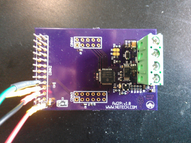
- An AlarmDecoder AD2PI
- NOTE: The AD2PI pictured is a development board with an extra long pin header. You'll need to solder the connection or go in through the bottom.
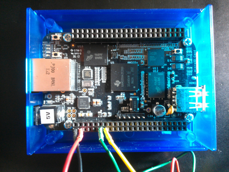
- A BeagleBone Black
- Wire & solder
Steps
- Make sure your BeagleBone and AD2PI are disconnected from power and the panel, respectively.
- Connect the pins between CONN2 on the AD2PI and P9 on the BeagleBone Black. See the images on the sidebar if you need a visual reference.
 AD2PI
AD2PI
 BeagleBone Black
 - Note the AD2Pi also supports 5v TTL just provide 5V and it will deliver 5v signals on TX/RX
- Connect power to your BeagleBone and boot it up.
- Enable UART4:
- echo BB-UART4 >/sys/devices/bone_capemgr.*/slots
- Your device should now show up as /dev/ttyO4.
- Test your device:
- Open the serial port with screen:
- screen /dev/ttyO4 115200
- Confirm communication with the device by rebooting it with =.
- Exit screen by typing Ctrl+A+K.
- Optional: Enable the overlay at boot:
- Add capemgr.enable_partno=BB-UART4 to /boot/uEnv.txt
- NOTE: I've been unable to actually get this to work yet. May be an issue with my kernel.


| Conn | AD2PI CONN2 Pin | BeagleBone P9 Pin |
|---|---|---|
| GND | 6 | 1 |
| 3.3V | 1 | 3 |
| RX | 10 | 11 |
| TX | 8 | 13 |